Developments
Temperature Impact of Insulation applied to Electrical Conductors

Executive Summary
Heat loss from a surface in contact with air depends on the temperature difference between the surface and the ambient air-mass and the level of agitation, as diffusion, convection or forced flow, within the air. The rate of loss from a given area is given by the temperature difference multiplied by a coefficient representing the characteristic of the air flow.
The near-zero electrical conductivity of plastic insulation is combined with poor thermal conductivity. If coating a large flat region, such as a wide bus-bar, with a thick layer of insulation, the restricted heat flow results in an elevated working temperature of the bus-bar and consequent increased resistance which both contribute to an elevated thermal equilibrium for heat loss from the outside surface.
The elevation of Temperature-Above-Ambient, θ, for such a large flat conductor, coated with a typical plastic insulation (thermal conductivity ITRO 0.25 W.m-1.°K-1), is comparatively small at about 2% per mm of insulation for diffusive or natural-convection cooling but can rise to 12% or more if forced-air-cooling ( ≥ 5m.s-1) is being used for the installation. More detailed calculations, below, show the direct dependence on Newtonian cooling and inverse dependence on insulation thermal conductivity but edge-effects and other geometric factors must also be considered for an engineering application.
Insulation on the outside surface of a cable or wire however increases cooling-surface area. This can improve cooling. Temperature has the same dependence on insulation and air-cooling, but this is now countered as the insulation increases net surface area. As a rule of thumb, in diffusive or natural-convection cooling, insulated conductors with a diameter less than about 100mm will run cooler with comparably thin insulation. Under forced-air-cooling ( ≥ 5m.s-1) this critical diameter is reduced to about 20mm; mittens are better than gloves at keeping hands warm, particularly in cold winds.
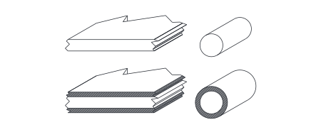
| Insulated planar conductors run warmer, especially if dependent on forced air-cooling. | Insulated wires have increased surface area and may run cooler under moderate air-cooling. |
Temperature Impact of Insulation Applied to Planar Electrical Conductors
This first calculation applies to a uniform thickness of material, e.g. plastic electrical insulation, applied to any planar electrical conductor or heat-source where edge-effects can be ignored.
Thickness of external insulating layer = t
Thermal conductivity of external layer = k
Newtonian Heat Transfer Coefficient of external surface = N
Ambient temperature = TA
Temperature of conductor surface without insulation = T0; WRT ambient, T0 – TA = 00
Temperature of conductor-insulation interface = T1; WRT ambient, T1 – TA = 01
Temperature of conductor-insulation outer surface = Ts; WRT ambient, Ts – TA = 0s
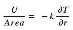
A conductor region of surface area A generates heat at the rate U and is in equilibrium with a surrounding air mass through Newtonian heat transfer. The energy flow per unit area is given by W = U/A and, at thermal equilibrium, this value must be the same for heat transfer through any applied insulation layer and from the external surface into the surrounding ambient.
This gives the temperature difference across the insulation layer as:
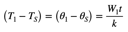
At the external surface of insulated conductor: 0s = W1/N
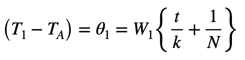
This gives the temperature difference between the insulated bus-bar and ambient as:
At conductor surface without insulation:
00 = W0/N
Case 1: Thermal Energy Dissipation Unaffected by Substrate Temperature
If the dissipation by the conductor remains the same, ( with W0 = W1 = W ) then the difference in temperature between an insulated and non-insulated conductor is given by:
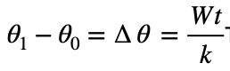
This can be referenced to the surface temperature of the non-insulated conductor to give:
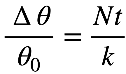
Typical convective Newtonian cooling (5W/m²°C) and polymer thermal conductivity (0.25 W/m°C) yield values for this expression in the region of 2% per mm of insulation layer thickness.
Case 2: Resistive Dissipation Dependent on Conductor Temperature
The electrical resistance of a conductor at working temperatures can be described by R = αϑ where α is a constant and temperature, ϑ, is referenced to a point of projected zero resistance. With working temperatures in the range 0-100°C, copper projects an “R-Zero” temperature c. -225°C and has a resistivity value of 1.7μΩcm at 20°C. This means that, with constant working current, the dissipation of a copper conductor is purely dependent on resistance and can be proportioned between ϑ values: W1/ϑ1=W2/ϑ2.
This now gives
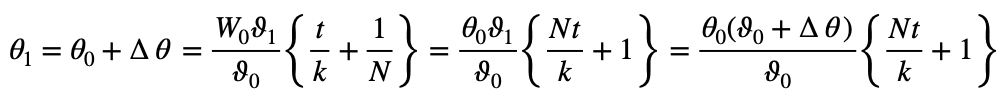
So that:
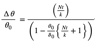
which, for small values of Nt/k and 00/ϑ0 can be approximated to
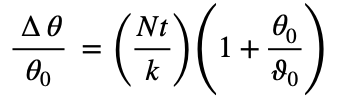
With bus-bar thermal equilibrium at 50°C in an ambient of 20°C the extra factor 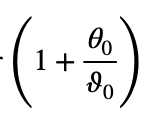
provides an 11% adjustment to the figure already obtained for dissipation independent of temperature.
Typical Coefficients for Thermal Conduction and Dissipation
|
Thermal Conductivity of Unfilled Plastics (W/mK) |
||
|
Acrylonitrile-butadiene-styrene |
ABS |
0.14-0.21 |
|
Acetal |
Delrin |
0.23-0.36 |
|
Epoxy |
|
0.19 |
|
Polyamide |
Nylon 6-11-12-66 |
0.24-0.3 |
|
Polyaramide |
Kevlar, Nomex fibers |
0.04-0.13 |
|
Polycarbonate |
PC |
0.19-0.22 |
|
Polytetrafluorethylene |
PTFE, Teflon |
0.25 |
|
Polyethylene terephthalate |
PET, Polyester |
0.15-0.4 |
|
Polyethylene LD |
Low density |
0.33 |
|
Polyethylene HD |
High density |
0.45-0.52 |
|
Polyimide |
Kapton |
0.10-0.35 |
|
Polymethylmethacrylate |
PMMA, Acrylic, Perspex, |
0.17-0.19 |
|
Polyurethane |
PUR |
0.29 |
|
Polyvinylchloride |
PVC |
0.12-0.25 |
Thermal conductivities of plastics are dependent upon process factors and treatments as well as intrinsic material properties.
Newtonian Heat Transfer Coefficients (NHTCs) for air cooling, in W/m²°C, can be anywhere between 0.5-1000 but typically have values ITRO 2-35 for convection.
Levels ITRO 0.5W/m²°C correspond to diffusion without bulk air movement when temperature differentials are low or air-flow is restricted.
Quoted Thermal Resistance values for natural convection with small finned heat-sinks correspond to NHTC values ITRO 6-8W/m²°C.
Air moving at 5ms¯¹ (11mph) provides an NHTC value ITRO 25W/m²°C.
Temperature Impact of Insulation Applied to Cylindrical Electrical Conductors
This calculation applies to a uniform thickness of material, e.g. plastic electrical insulation, applied to any cylindrical heat source where end-effects can be ignored.
Cylindrical radius of conductor = a
Thickness of external layer = t
Thermal conductivity of external layer = k
Newtonian Heat Transfer Coefficient of external surface = N
Ambient temperature = TA
Conductor surface temperature without insulation = T0; WRT ambient, T0 – TA = 00
Surface temperature of conductor beneath insulation = T1; WRT ambient, T1 – TA = 01
Surface temperature of insulated conductor = TS; WRT ambient, TS – TA = 0S
A conductor of length l generates heat at the rate U and is in equilibrium with a surrounding air mass through Newtonian heat transfer.
At conductor surface without insulation: 00 = U/2πN/a
At external surface of insulated conductor: 00 = U/2πNl(a+1)
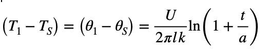
Heat flow within a material is described by:
A solution with cylindrical symmetry gives the temperature difference across the insulation:
The change in the conductor surface temperature caused by adding insulation is then given by:
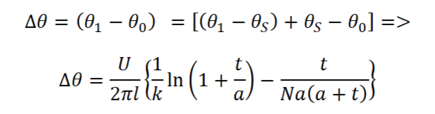
Probably more convenient is the fractional change in temperature WRT ambient:
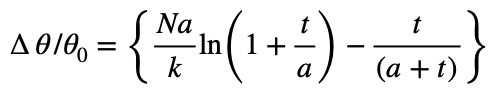
Dependent upon the relative values of the variables and parameters, this can be negative. It therefore illustrates the conditions for improved cooling when the effect of increased exposure area is superior to the coating’s thermal resistance.
If the insulation is thin, then t < a and r = (a + t) give the simplified form:
![]()
This indicates improved cooling for conductors with overall radii below a critical value:
r = rcrit = k/N
A thin nylon layer, (thermal cond. 0.25 W/m°C) enhances convective cooling on cylindrical conductors if the overall radius falls below the following values:
|
Convection |
Newtonian HTC |
rcrit |
∅crit |
|
Air |
W/m²°C |
Conductor mm |
Conductor mm |
|
Poor |
1 |
250 |
500 |
|
Low Natural |
5 |
50 |
100 |
|
High Natural |
10 |
25 |
50 |
|
Forced, 5ms¯¹ |
25 |
10 |
20 |
Referring to this table and the simplified expression above, insulated conductors are commonly well below the critical size, especially in situations with poor convection. Wherever this is the case then, N/k ≪ 1/r, and the simplified expression for the temperature change due to applied insulation becomes:
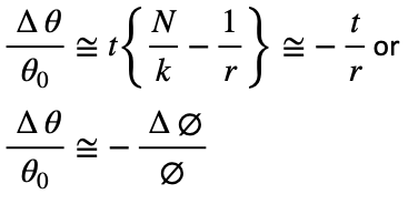
This is a rather surprising result demonstrating an improvement in cooling that is largely independent of material. It is applicable when the wires compare favourably with the criteria described for small size, thin insulation and moderate Heat Transfer Coefficient.
Make an enquiry
LML Products is the most trusted supplier of busbar, cable, connector & earth bar in the UK. We’re ready to talk about your project.
Or Call: 01249 810000